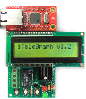
iTelegraph v1.2 Assembly Instructions:
Tools you will need:
- Soldering iron with a fine tip, 35 Watts or less for electronics
work
- 60/40 rosin core solder (Do not use acid core solder on this kit!)
- Diagonal cutters
- Optional: Desoldering wick or desoldering pump, multimeter, desk clamp
for holding work pieces steady
Parts List:
Go through the parts list and identify the components to make sure all the parts are there.
| Quantity: |
Designators: | Component: |
| 5 | C1, C2, C5, C6, C7 |
0.1 uF ceramic capacitor |
| 2 | C3, C4 |
10uF electrolytic capacitor |
| 2 | D1, D4 |
1N4002 diode |
| 1 | D2 |
Red LED |
| 1 | D3 |
Green LED |
| 1 | IC1 |
Atmega328 MCU 28 pin DIP chip and socket |
| 1 | IC2 |
LM7805 5V regulator |
| 1 | IC3 |
MCP1703 3.3V regulator |
| 1 | J1 |
2.1mm DC Power Jack |
| 2 | J6, J7 |
3 position screw terminal blocks |
| 1 | JP3 |
ISP Programming Header (2x3 pins) |
| 1 | JP7 |
FTDI Programming Header (1x6 pins) |
| 2 | LC1, LC2 |
8 pin socket for LCD |
| 1 | R1 |
10k resistor (brown, black, orange, gold) |
| 1 | R2 |
1k resistor (brown, black, red, gold) |
| 4 | R3. R4. R5. R7 |
2.2k resistor (red, red, red, gold) |
| 2 | R6, R9 |
33 ohm resistor (orange, orange, black, gold) |
| 1 | RLY1 |
5V relay |
| 3 | S1, S2, S3 |
push button switch |
| 1 | SP1 |
audio transducer |
| 2 | T1, T2 |
PN2222 NPN transistor, TO-92 |
| 1 | X1 |
16 Mhz ceramic resonator |
| 4 | |
10 pin sockets for Wiznet Module |
Assembly:
A few notes on soldering:
- Heat the joint, not the solder directly. When heated properly by the iron, the solder should melt and flow into the joint once it is applied.
- Always use enough heat when soldering, but do not overheat. The joints on this board should not need heating for more than 5 seconds each. If it takes longer, then your iron is not putting out enough heat, or the iron tip is contaminated. Wipe the tip on a wet sponge and try again.
- A good solder joint is shiny. A dull, grainy-looking joint is indicative of a cold joint. Cold solder joints make poor mechanical and electrical connections. They can be fixed by reheating the joint, removing the old solder and resoldering the connection with new solder.
- Keep the soldering iron tip clean. Wipe the iron tip on a moist (not soaking wet) sponge frequently to remove old flux, dross (oxidized solder), and other contaminants that can ruin your connection.
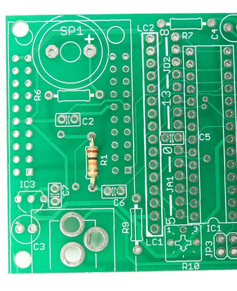
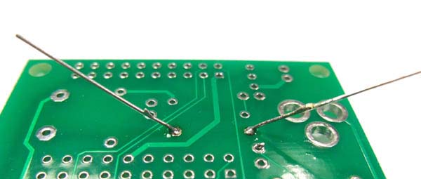
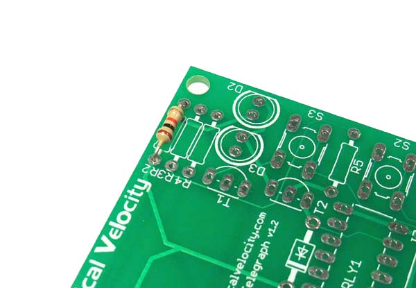
Ok - let's begin! Locate R1 on the PCB. Bend the leads of the 10k resistor 90 degrees. Insert them into the two holes for R1. Bend the leads of R1 on the other side of the PCB so that it doesn't fall out when you turn the board over. Resistors are not polarized, so they can be inserted either way.
Turn the PCB over, and solder the resistor.
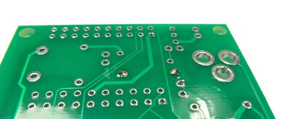
Trim off the leads of the resistor.
Install (Insert, solder and trim) the 1k resistor R2.
Install 2.2k resistors R3 and R4.
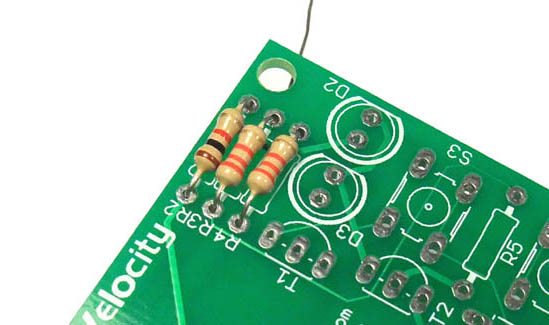
Install 2.2k resistor R5.

Install 33 ohm resistors R6 and R9.
Install ceramic capacitor C1. These capacitors are not polarized so they can be installed either way.
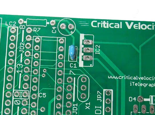
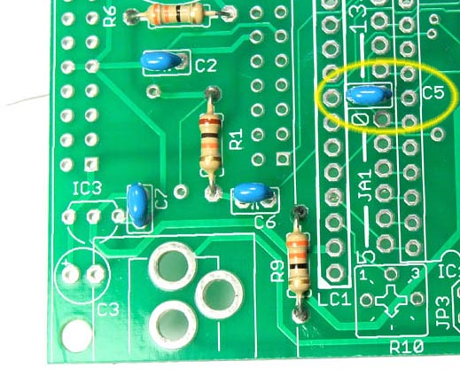
Install ceramic capacitors C2, C5, C6, and C7. Note that C5 is located in the middle of a large number of holes for connectors and sockets. Make sure the capacitor is inserted into the correct holes as shown.
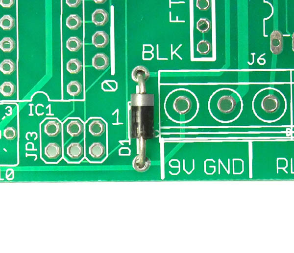
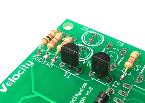
Install diode D1. Note that diodes are polarized, and have a silver band indicating the cathode. Ensure the band on the diode matches the band shown on the PCB.
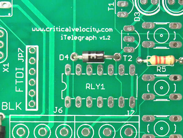
Install diode D4. Ensure the band on the diode matches the band shown on the PCB.
Install the PN2222A transistor T1. Make sure you are installing the transistor and not the voltage regulator since they look similar! The transistor has one flat side. Make sure the flat side matches the drawing on the PCB.
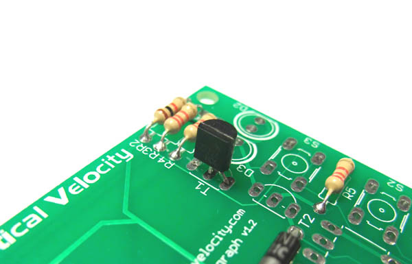
Install transistor T2, again making sure the orientation is correct. Transistors T1 and T2 are used to switch the speaker and the relay.
The transistors are used here to amplify the samll current produced by the microcontroller pin into a large current that can drive a relay or a speaker.
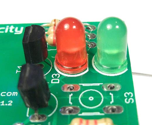
Install the red light emitting diode (LED). LED's are polarized.
There is a long and a short lead. The shorter lead should go towards the flat side indicated on the PCB. The LED also has one side flat - this should correspond with the drawing on the PCB.
This LED is used to indicate the relay output.

Install the green LED. Make sure that the flat side of the LED matches the flat side shown on the PCB.
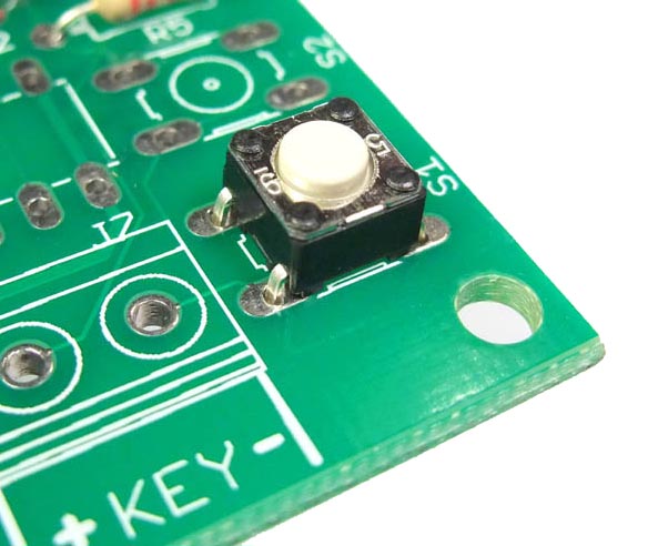
Install pushbutton S1. Orientation does not matter for these switches.
Caution! The leads are already bent by the manufacturer such that they will stay in the PCB once inserted. However, it does require some force to insert, so please do not put your fingers underneath the PCB while you push the switch in!
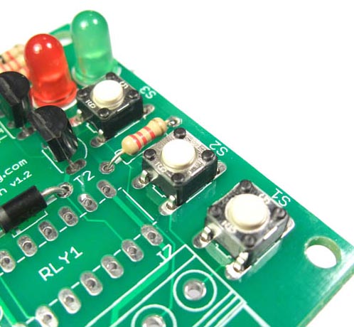
Install pushbuttons S2 and S3.
Caution! The leads are already bent by the manufacturer such that they will stay in the PCB once inserted. However, it does require some force to insert, so please do not put your fingers underneath the PCB while you push the switch in!
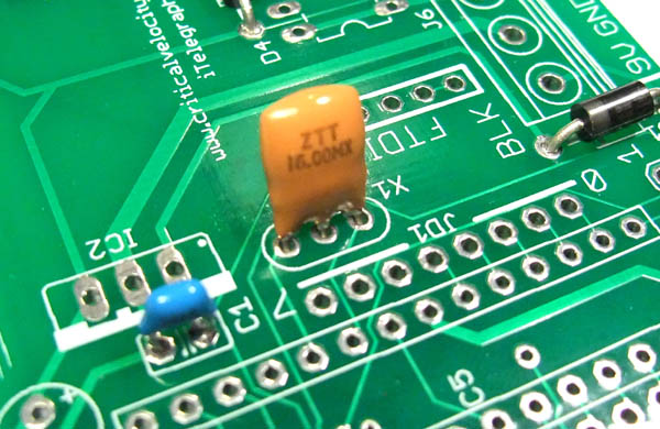
Install ceramic resonator X1. This is used by the microcontroller to generate a stable 16 Mhz clock frequency. Orientation does not matter as the part is symmetrical.
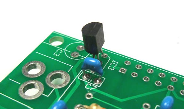
Install voltage regulator IC3. Ensure that the flat side of the regulator matches the drawing on the PCB. This should be installed as low as reasonably possible on the PCB to ensure it does not interfere with the Ethernet module that will be installed over it.
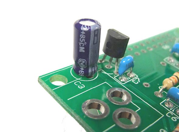
Install capacitor C3. These electrolytic capacitors are polarized. One side of the capacitor has a stripe showing the negative terminal. Ensure that it is correctly oriented before soldering.
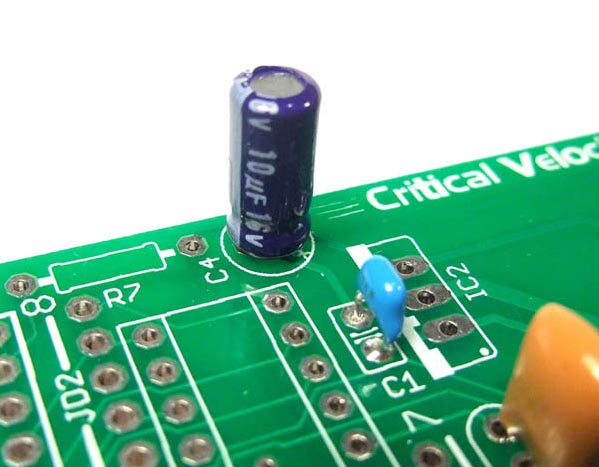
Install capacitor C4. Ensure that it is correctly oriented before soldering.
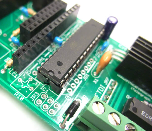
Install the socket for IC1. There is a notch on one end of the socket. This notch should match the drawing on the PCB.

You can bend a few pins of the IC socket to keep them from falling out during soldering.
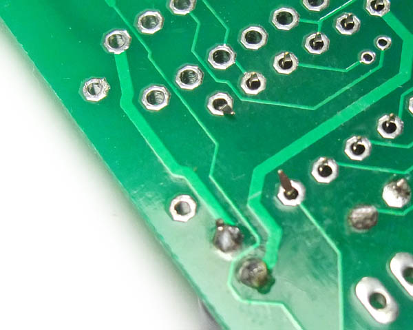
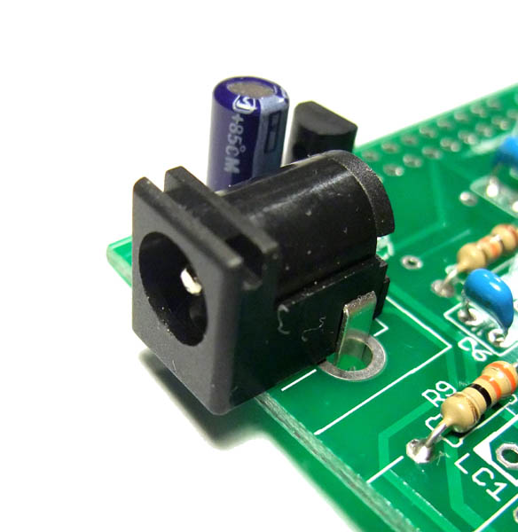
Install the power jack. Use enough solder to ensure a good mechanical as well as electrical connection. Since the leads cannot be bent easily, you can solder one of the leads from the top of the PCB. Then you can turn it over and complete the other joints without the jack falling out.
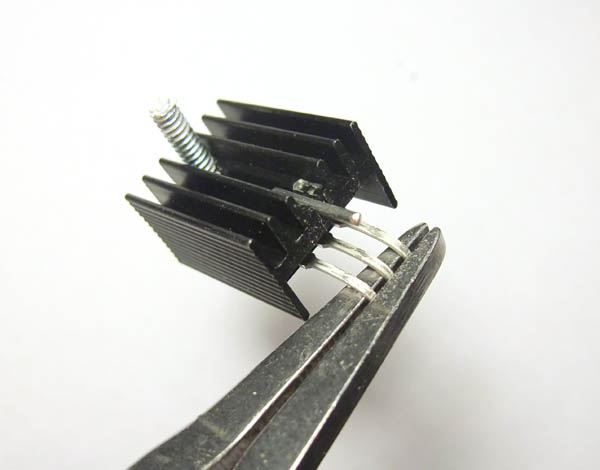
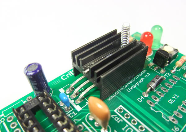
Prepare the leads of the 5V regulator. The regulator and heatsink need to be installed horizontally, so bend the leads 90 degrees towards the front of the regulator with a pair of needle nose pliers. The regulator will be installed face down.
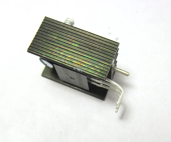
Install the regulator as shown. It should be installed face down.
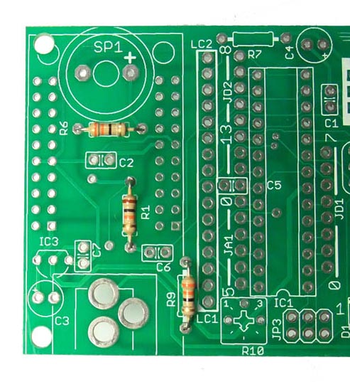
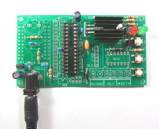
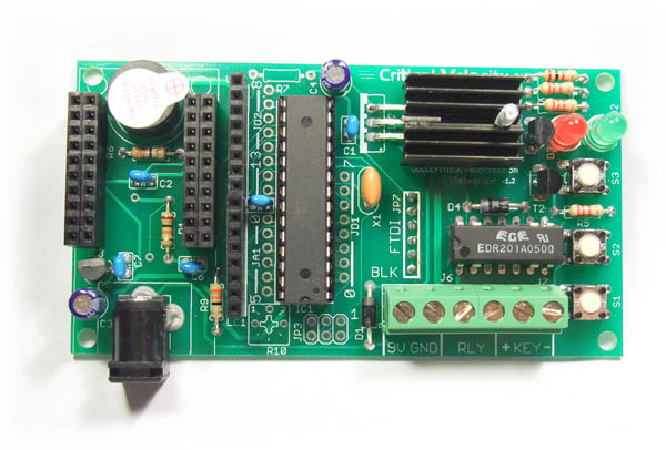
Ok - now that we have most of the components installed, let's do a power test. But before we do a power test, check that your board looks like the one pictured here.
Now plug the power adapter into the wall, and plug the coax plug into the DC power jack. If all is well, the green LED should light. Check for any signs of heating or smoke. When all is well, continue on.
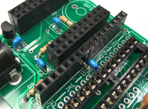
Install the sockets for the Ethernet module. It will take four 10-pin sockets to make up the entire Ethernet socket.
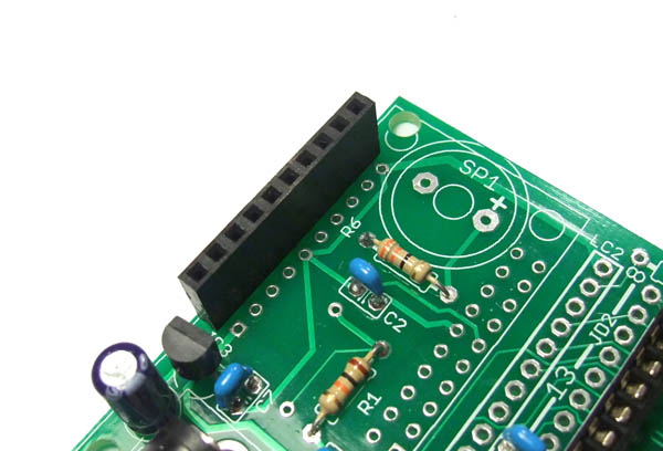
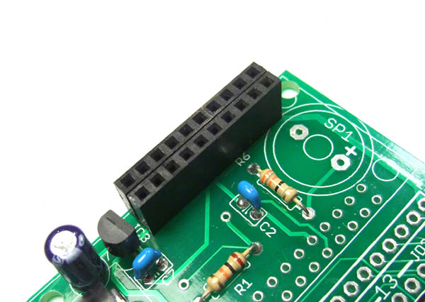
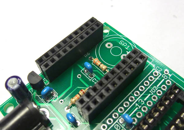
Install the sockets for the LCD. It will take two 8-pin sockets installed in a row to make up the entire LCD socket.
Install the speaker. The speaker has a positive and a negative terminal. Make sure it is oriented to match the drawing on the PCB.
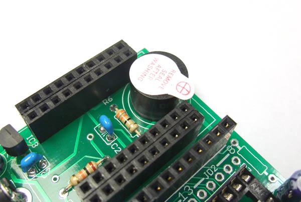
Install the relay RLY1. The relay is used to switch external sounders. The relay is polarized - ensure that the notch on the relay matches the notch shown on the PCB.
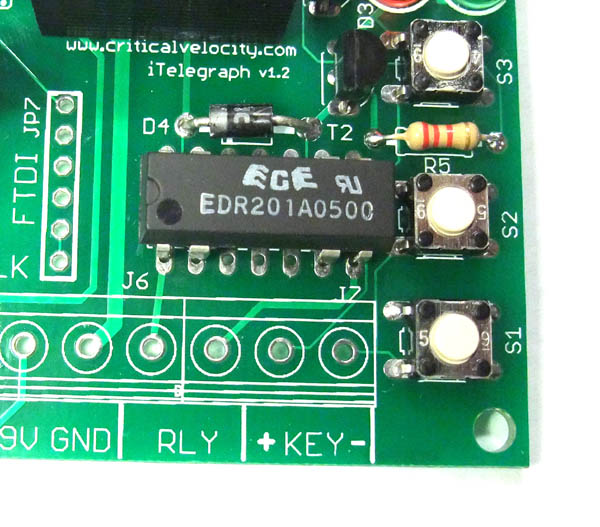
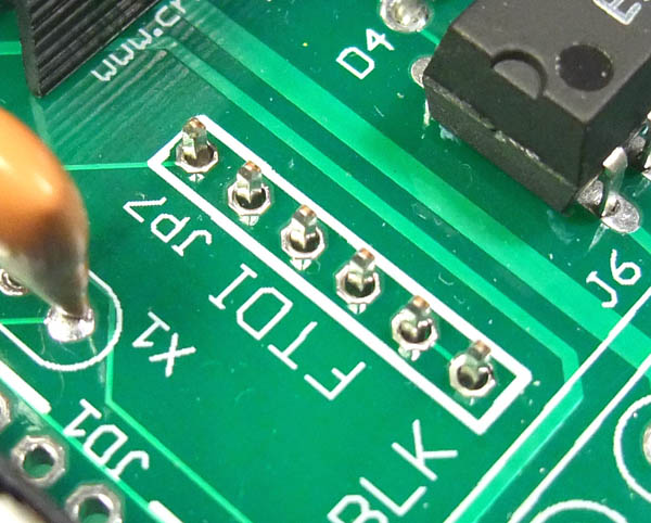
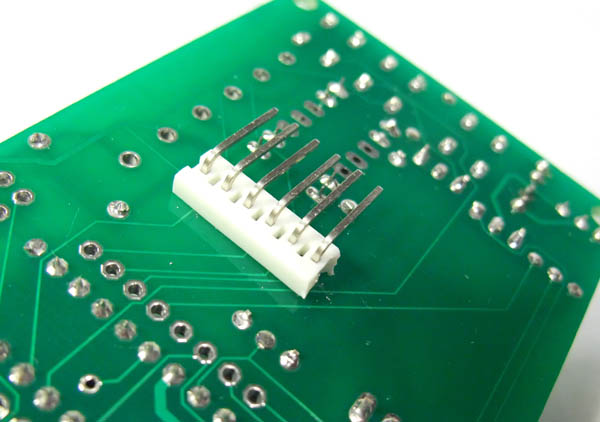
If you plan on modifying the code and uploading it to the iTelegraph, you can install the FTDI header. To make programming easier with large LCD's, a right angle connector can be installed onto the back of the PCB.
Locate the FTDI connector holes on the top of the PCB. Insert the right angle header from the bottom, and solder it on top.
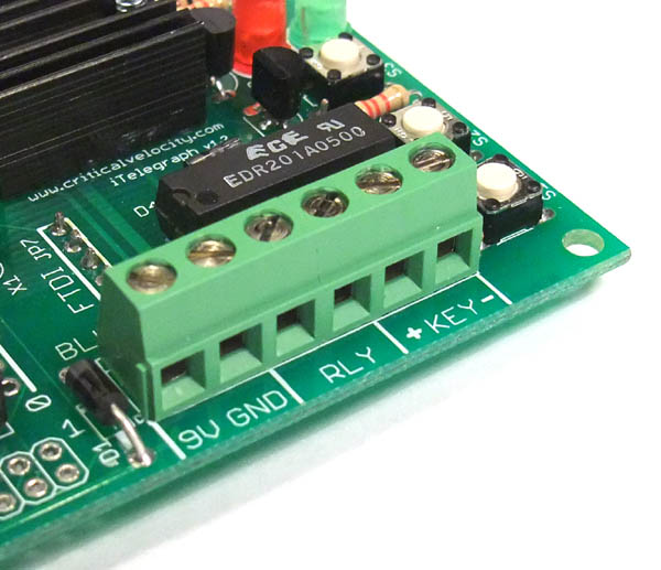
There are two separate 3-pole terminal blocks. Join the terminal blocks together by sliding one over the other, making sure the tab on one fits into the slot of the other.
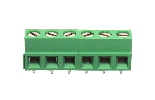
Install the terminal blocks as shown.
Now that all the parts are soldered, we can start plugging in the components. Install the Atmega microcontroller into the socket. Make sure the notch on the chip matches the notch on the socket.
With the microcontroller installed, the board should look like the following:
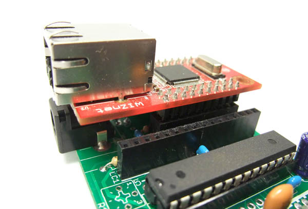
Now plug in the Ethernet module. The Ethernet jack should be on the same side as the power jack.
Plug in the LCD module. You're Done!
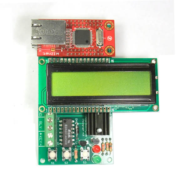
Double check each connection to make sure there are no cold solder joints. Once everything looks good, you are ready to start testing!
|