iTelegraph v1.2 Manual:
Tools you will need:
- Completed iTelegraph Main Board
- Wiznet Ethernet Module and LCD module - if you bought the complete kit, these are included
- 9VDC power supply - wall adapter or other supply
- Ethernet cable and Ethernet hub/switch or router to plug into
- Computer with connection to the same router or switch for initial testing
Initial Testing:
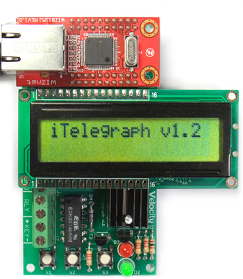
Make sure the Wiznet module and LCD modules are correctly installed onto the main board. Plug in the Ethernet cable, and then plug in the power supply. The initial bootup screen should show 'iTelegraph v1.2'.
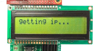
Check that the Ethernet link LED's are lit on the Wiznet module. iTelegraph comes with DHCP support, so network configuration can be made very easy.
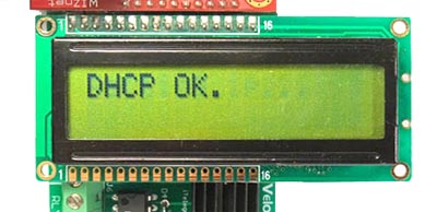
Once an IP address is acquired, "DHCP OK" should appear. If unable to obtain an IP, check to make sure the Ethernet cable and connection is working. Try unplugging and plugging the power cord back in to the iTelegraph to reset it. If DHCP is not available on your network, you can still manually configure the network settings. See the "Menu Options" section to configure the network.
iTelegraph will then try to connect to its last known remote IP. This will most likely be invalid since no IP has been entered yet. It will say "Connect Failed"
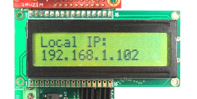
The menu systems will refer to the three pushbuttons on board as 1, 2, and Key (S3). To display current status, hit S2. It will show the various parameters, such as local IP, gateway, local port, etc.
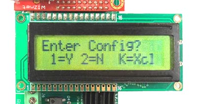
Hit S1 to enter the main menu. It will ask whether you want to enter the remote IP. Hit S1 for Yes.
Now it will ask whether you want to enter the configuration menu. Hit S1 for Yes.
The screen will show that it has entered the Setup Menu, and it will ask if you want to enable DHCP.
To enable it, hit S1 for Yes. Hit S2 if you do not have DHCP on your network and want to manually configure the network. To keep the setting as is, hit S3 to cancel and move to the next parameter.
For initial testing, go through the configuration options to enable the speaker and enable local echo.
Menu Options:
The following is a summary of the various configuration options:
Enable DHCP?
This option sets up DHCP. Hit S1 to enable, S2 to disable, or S3 to skip to the next menu.
Config Network?
This is the manual network configuration. Skip this if DHCP is enabled.
Local IP:
Specify the local IP address. You can get this from your local network admin. S2 increases the number, S1 decreases. Hit S3 to move to the next octet.
Gateway:
Specify the gateway. You can find this information from a computer on the same network by running ipconfig on a Windows computer.
Subnet:
Specify the subnet mask. You can find this information from a computer on the same network by running ipconfig on a Windows computer.
Change Ports?
By default, telnet port 23 is used for iTelegraph. You can change this to any port you want. Hit Yes to configure ports.
Listening Port:
This is the listening port. If using over the Internet, be sure your firewall has port forwarding so that incoming connections are routed directly to your iTelegraph. Use buttons S1 and S2 to change the port.
Remote Port:
This is the remote port to connect to.
Enable Speaker?
Hit Yes to enable the onboard oscillator and speaker. Enable it for initial testing. If an external sounder or oscillator is connected, set this option to No.
Enable Echo?
This option turns on or off the local echo option. If enabled, pressing the key activates the local sounder.
Cfg MAC Address?
iTelegraph comes with a default MAC Address which uniquely identifies the device on the network and is used by the DHCP server to assign an IP address. If using more than one iTelegraph on the same local area network, change this address to something else. There are 255 possible addresses.
Once out of the menu, hit S3. If the speaker and local echo are enabled, you will hear a tone, and the red LED will light. Great! You have a code practice oscillator!
Testing on the local network:
Let's try it on the network. Hit S2 to show the network parameters. We'll connect to the unit via Telnet and activate the sounder through the network. From the start menu on a Windows computer, run the telnet command. Or you can just type TELNET from the command prompt.
From the telnet window, type the following:
open 192.168.1.102 23
where 192.168.1.102 is the IP address of the iTelegraph on your network. 23 is port we want to connect to. You can leave out the 23 since telnet defaults to port 23. If you change the default port on the iTelegraph, you'll need to specify it at the prompt.
It should connect immediately. The telnet cursor will move to the top of the screen, but the existing text may still be showing. Try sending a command by typing a "1" (without the quotes) into the telnet window. You should see a "1" show up followed by a period. The period is acknowledgement by the iTelegraph. You should now hear a tone, and the red LED should light.
The "1" is the command to activate the sounder. To shut off the tone, type a "2".
Try hitting S3 on the iTelegraph. You should start seeing 1's and 2's appearing through your telnet window.
Great - it works on the network!
Connecting an external key and sounder:
An external key makes it much easier to send Morse code. Connect a key (basically a simple switch) to the terminals labeled KEY.

An external sounder completes the telegraph setup. There are many ways to hook an external sounder to the unit. The iTelegraph contains a relay (an electronically operated switch) that can be used to control an external device.
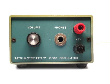
Let's say you have a Code Practice Oscillator (CPO) you want to use, like this vintage Heathkit CPO.
Just connect two wires from the terminals labeled "RLY" on the iTelegraph to the KEY terminals on the CPO. Once done, go through the configuration menu to disable the speaker. Keep the local echo enabled since we still want the local key to affect the local sounder (the CPO in this case).
Now hitting the key will activate the CPO.
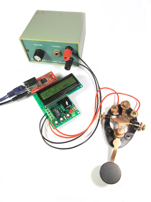
Note the red wires going from the key to the terminals labeled "KEY". The black wires go from the CPO to the terminals labeled "RLY".
Connecting to a remote iTelegraph:
The iTelegraph was designed to connect to other iTelegraphs.
Press S1 to enter the main menu. Hit S1 for Yes when asked if you want to enter the remote IP.
Now use S1 and S2 to change the remote IP, and the key or S3 to move on to the next octet. Once entered, it will try connecting to the IP address.
It will say "Connected To:" and the IP address when connected. Pressing the local key will now activate the remote iTelegraph's sounder.
Now you can have a virtual "dedicated telegraph line" to your friends anywhere in the world!
Connecting antique sounders:
Antique sounders can be easily connected as well. Put those antique telegraphs to use!
The most common type of sounder consists of an electromagnet and a spring-loaded moving arm that hits the magnet when activated. These create a click sound once turned on, and another click as it deactivates.
To use such a sounder, an external power supply is needed to drive the coil. Find out how much current the coil is rated for. Depending on the type of sounder and where it was used, the coil resistances vary from low to high resistance coils for higher voltage lines.
You could use a variable power supply to determine the best operating voltage and current, and hook that up in series with the coil to the RLY terminals. The iTelegraph's relay will act as a switch and control power to the coil.
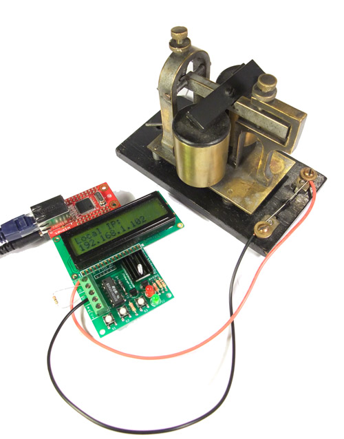
The key is not shown for clarity.
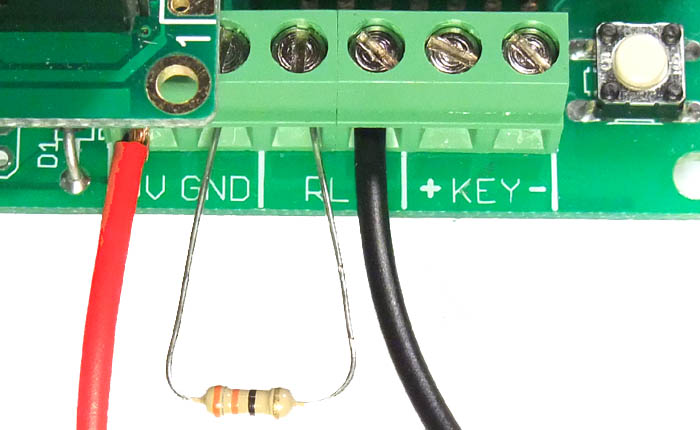
You can also use the iTelegraph's 9VDC supply for the coil. The terminals 9V and GND on the mainboard are internally connected to the 9VDC power supply. Once you find the correct voltage, you can then use a dropping resistor to lower the voltage to the coil to ensure it is operating correctly.
Electromagnets are inductors - and when the current through an inductor is abruptly shut off, the current will try to keep flowing. To try to maintain that current, the voltage across the coil will increase to very high levels, even thousands of volts! To prevent that voltage from damaging other electronics, we need to install a diode across the coil. The diode should be installed against the flow of current in parallel with the coil. During normal activation, no current flows through the diode. However, once the switch turns off, the current in the coil has a place to go - through the diode.
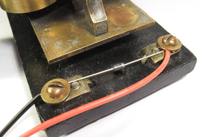
Notice the diode's cathode goes towards the positive side - the red wire.
The following is a diagram showing the wiring of the coil to the iTelegraph. The resistor R1 is chosen to drop the required voltage for the coil, and should be rated to handle the wattage dissipated by the voltage drop. In some cases, R1 may be omitted if it is not necessary.
|


