LCD Shield v1.0 Manual:
Tools you will need:
Initial Testing:
Plug the jumper into the lower two pins of JP1, as shown. This connects the RW pin of the LCD to ground. We will use this configuration we will use for initial testing.
If the jumper is installed across the pins labeled LCRW, then the RW pin will be connected to Arduino Digital Pin 6.

Plug the LCD Module into the LCD Shield. Make sure pin 1 of the LCD lines up with pin 1 of the connector on the LCD Shield. Use connectors LC1 and LC2 for the bottom mount configuration, and LC3 and LC4 for the center mount configuration.

Plug the shield into the Arduino and upload the demo sketch. The LCD should say "LCD Shield v1.0"
Congratulations! You can now display text using your Arduino!
Using the Accessories:
The LCD Shield comes with a speaker and a pushbutton. In addition, the LCD backlight can also be activated.
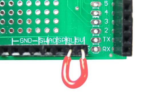
To turn on the backlight, connect a wire between the BL pin and the 5V pin at the accessories header. If your backlight requires a current limiting resistor, then connect the resistor in place of the wire between BL and 5V.
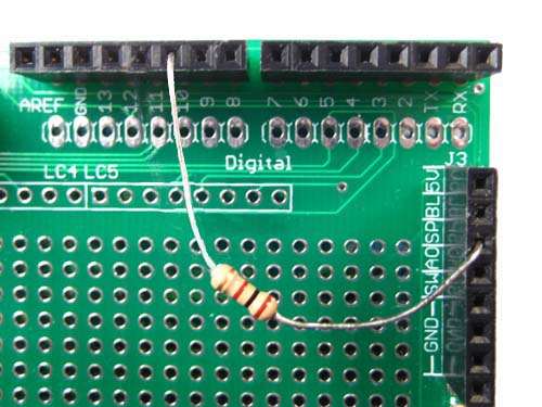
The on board speaker can be used by connecting a wire to the SP pin on the accessories header. The speaker can be driven by an audio amplifier, or by an Arduino pin through a resistor. To connect to an Arduino pin, connect a 100 ohm resistor between the pin and the speaker. This will limit the maximum current out of the Arduino pin.
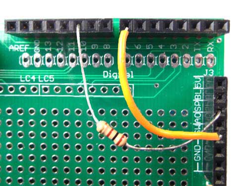
The on board pushbutton can be accessed via the accessories header. One side of the pushbutton is internally connected to ground. Connect a wire between the SW pin and the Arduino pin you want to use. For the demo sketch, connect the SW pin to Arduino Digital Pin 7.
With the demo sketch loaded, push button SW1. You should hear a tone coming from the speaker. Let go of the button and the tone should stop.
That concludes the initial testing. Modify the code and bring your project to life!
|


